How To Make Use Case Diagram In Smartdraw
Create a UML use case diagram
Visio Plan 2 Visio Plan 1 Visio Professional 2021 Visio Standard 2021 Visio Professional 2019 Visio Standard 2019 Visio Professional 2016 Visio Standard 2016 Visio Professional 2013 Visio 2013 Visio Premium 2010 Visio 2010 Visio Standard 2010 Visio 2007 Visio Standard 2007 More...Less
You can create a UML use case diagram in Visio to summarize how users (or actors) interact with a system, such as a software application. An actor can be a person, an organization, or another system.
Use case diagrams show the expected behavior of the system. They don't show the order in which steps are performed. (Use a sequence diagram to show how objects interact over time.)

Defining the system boundary determines what is considered external or internal to the system.
An actor represents a role played by an outside object. One object may play several roles and, therefore, is represented by several actors.
An association illustrates the participation of the actor in the use case.
A use case is a set of events that occurs when an actor uses a system to complete a process. Normally, a use case is a relatively large process, not an individual step or transaction.
Create a new use case diagram
-
On the File tab, point to New.
-
in the Search box, type UML use case.
-
From the search results, select UML Use Case.
-
In the dialog box, select the blank template or one of the three starter diagrams. (A description of each one is shown on the right when you select it.) Then select either Metric Units or US Units.
-
Select Create.
-
The diagram opens. You should see the Shapes window next to the diagram. A UML Use Case stencil is open in the Shapes window.
(If you don't see the Shapes window, go to View > Task Panes and make sure that Shapes is selected. If you still don't see it, click the Expand the Shapes window button on the left.)
Add a subsystem to the use case diagram
-
Drag a Subsystem shape onto the drawing page. The subsystem can represent your entire system or a major component.
-
Double-click the Subsystem shape, and then type a new name for the for it, or press the Delete key to delete the existing name. Click outside the shape on the drawing page.
-
To resize the subsystem, select the shape, and then drag a selection handle.
Add shapes and connectors to the diagram
-
Drag Use Case shapes
 from the UML Use Case stencil and place them inside the subsystem boundary, and then drag Actor shapes
  to the outside of the subsystem boundary.
 -
Use connector shapes to indicate relationships between shapes in the diagram. There are five connectors available:
Connector
Description
Association
Shows the relationship of an actor to a use case.
Dependency

Indicates that one use case has a dependency on another.
Generalization
Indicates that a use case is a specific way to achieve goals of the general use case.
Include

Shows how a use case is broken into smaller steps.
Extend

Shows that one use case adds functionality to another.
Example: To indicate a relationship between an actor and a use case
-
In a use case diagram, drag an Association connector shape onto the drawing page.
-
Glue one endpoint of the Association shape to a connection point on an Actor shape. Glue the other endpoint to a connection point on a Use Case shape.
-
See Also
For more information about use case diagrams (and procedures for using Microsoft Visual Studio to create use case diagrams), go to UML Use Case Diagrams: Guidelines.
Create a new use case diagram
-
Open Visio for the web.
-
Near the upper right corner of the page, select More templates.
-
In the Gallery, scroll down to the UML Use Case row.
The first item in the row represents a blank template plus the companion stencil. The other items in the row are sample diagrams that have some shapes already drawn to help you get started quickly.
-
Click any item to see a larger preview.
-
When you find the diagram you want to use, click its Create button.
The new diagram, with the related stencil, opens in your browser.
Add a subsystem to the use case diagram
-
Drag a Subsystem shape onto the drawing page. The subsystem can represent your entire system or a major component.
-
Double-click the Subsystem shape, and then type a new name for the for it, or press the Delete key to delete the existing name. Click outside the shape on the drawing page.
-
To resize the subsystem, select the shape, and then drag a selection handle.
Add shapes and connectors to the diagram
-
Drag Use Case shapes
from the Use Case stencil and place them inside the subsystem boundary -
Drag Actor shapes
to the outside of the subsystem boundary. -
Use connector shapes to indicate relationships between shapes in the diagram. There are five connectors available:
Connector
Description
Association
Shows the relationship of an actor to a use case.
Dependency
Indicates that one use case has a dependency on another.
Generalization
Indicates that a use case is a specific way to achieve goals of the general use case.
Include
Shows how a use case is broken into smaller steps.
Extend
Shows that one use case adds functionality to another.
Example: To indicate a relationship between an actor and a use case
-
In a use case diagram, drag an Association connector shape onto the drawing page.
-
Glue one endpoint of the Association shape to a connection point on an Actor shape. Glue the other endpoint to a connection point on a Use Case shape.
-
-
Visio for the web saves automatically. To rename a drawing, double-click to select the default name (such as Drawing1) at the top of the drawing and then type a new name over it.
See Also
For more information about use case diagrams (and procedures for using Microsoft Visual Studio to create use case diagrams), go to UML Use Case Diagrams: Guidelines.
Create a new use case diagram
-
On the File tab, point to New.
-
in the Search box, type UML use case.
-
From the search results, select UML Use Case.
-
In the dialog box, select the blank template. Then select either Metric Units or US Units.
-
Select Create.
-
The diagram opens. You should see the Shapes window next to the diagram. A UML Use Case stencil is open in the Shapes window.
(If you don't see the Shapes window, go to View > Task Panes and make sure that Shapes is selected. If you still don't see it, click the Expand the Shapes window button on the left.)
Add a subsystem to the use case diagram
-
Drag a Subsystem shape onto the drawing page. The subsystem can represent your entire system or a major component.
-
Double-click the Subsystem shape, and then type a new name for the for it, or press the Delete key to delete the existing name. Click outside the shape on the drawing page.
-
To resize the subsystem, select the shape, and then drag a selection handle.
Add shapes and connectors to the diagram
-
Drag Use Case shapes from the UML Use Case stencil and place them inside the subsystem boundary, and then drag Actor shapes to the outside of the subsystem boundary.
-
Use connector shapes to indicate relationships between shapes in the diagram. There are five connectors available:
Connector
Description
Association
Shows the relationship of an actor to a use case.
Dependency
Indicates that one use case has a dependency on another.
Generalization
Indicates that a use case is a specific way to achieve goals of the general use case.
Include
Shows how a use case is broken into smaller steps.
Extend
Shows that one use case adds functionality to another.
Example: To indicate a relationship between an actor and a use case
-
In a use case diagram, drag an Association connector shape onto the drawing page.
-
Glue one endpoint of the Association shape to a connection point on an Actor shape. Glue the other endpoint to a connection point on a Use Case shape.
-
See Also
For more information about use case diagrams (and procedures for using Microsoft Visual Studio to create use case diagrams), go to UML Use Case Diagrams: Guidelines.
-
On the File tab, point to New.
-
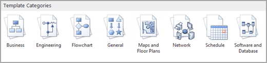
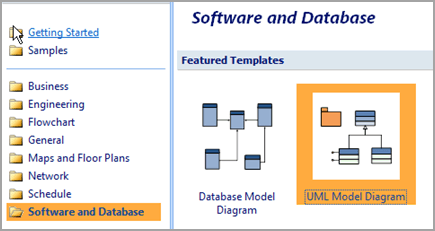
Under Template Categories, click Software and Database.
-
Click UML Model Diagram. A blank drawing page appears.

-
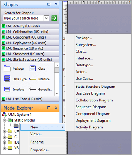
In the tree view, right-click the package or subsystem in which you want to include a use case diagram, then point to New, and then click Use Case Diagram.
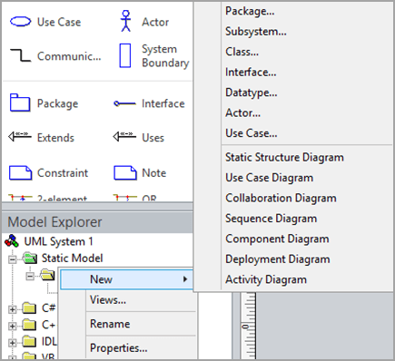
A blank page appears, and the UML Use Case stencil becomes the top-most stencil. An icon representing the diagram is added to the tree view.
Note:If the tree view is not visible, on the UML tab, in the Show/Hide group, select Model Explorer.
-
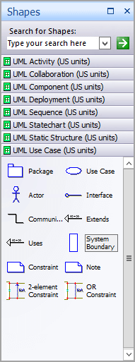
To indicate a System Boundary in a use case diagram
-
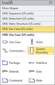
Drag a System Boundary shape onto the drawing page.
-
Double-click the System Boundary shape, and then type a new name for the system or press the DELETE key to delete the existing name. Click outside the shape on the drawing page.
-
To resize the system boundary, select the shape, and then drag a selection handle.
-
-
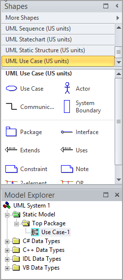
Drag Use Case shapes from the Use Case stencil and place them inside the system boundary, and then drag Actor shapes to the outside of the system boundary.
-
Use Communicates shapes to indicate relationships between use cases and actors.
To indicate a relationship between an actor and a use case
-
In a use case diagram, drag a Communicates shape onto the drawing page.
-
Glue one endpoint
 of the Communicates shape to a connection point
  on an Actor shape. Glue the other endpoint to a connection point on a Use Case shape.
 -
If you want to add an arrow to indicate the flow of information, do the following:
-
Double-click the Communicates shape, then, under Association, click the end you want to edit, and then click Properties.
-
In the Association End category, check IsNavigable, click OK, then click OK again.
-
Right-click the Communicates shape and click Shape Display Options. Under End options, select End navigability, and then click OK.
-
-
-
Use Uses and Extends shapes to indicate the relationships between use cases.
To indicate a uses relationship between two use cases
-
In a use case diagram, drag a Uses relationship shape onto the drawing page.
-
Glue the Uses endpoint without an arrowhead to a connection point
on the Use Case shape that uses the behavior of the other use case. -
Glue the Uses endpoint (with an arrowhead) to a connection point on the use case being used.
-
Double-click the Uses shape to open the UML Generalization Properties dialog box. Add property values, and then click OK.
To indicate an extends relationship between two use cases
-
In a use case diagram, drag an Extends shape onto the drawing page.
-
Glue the Extends endpoint
without an arrowhead to a connection point on the use case providing the extension. -
Glue the Extends endpoint with an arrowhead to a connection point on the base use case.
-
Double-click the Extends shape to open the UML Generalization Properties dialog box. Add the property values, and then click OK.
-
-
Double-click any shape (except the System Boundary shape) to open its UML Properties dialog box where you can add a name, attributes, operations, and other property values.
-
Save the diagram.
-
On the File menu, point to New, point to Software and Database, and then click UML Model Diagram.
-
In the tree view, right-click the package or subsystem in which you want to include a use case diagram, point to New, and then click Use Case Diagram.
A blank page appears, and the UML Use Case stencil becomes the top-most stencil. An icon representing the diagram is added to the tree view.
Note:If the tree view is not visible, on the UML menu, point to View, and then click Model Explorer.
-
To indicate a system boundary in a use case diagram
-
Drag a System Boundary shape onto the drawing page.
-
Double-click the System Boundary shape, and then type a new name for the system or press the DELETE key to delete the existing name. Click outside the shape on the drawing page.
-
To resize the system boundary, select the shape, and then drag a selection handle.
-
-
Drag Use Case shapes from the Use Case stencil and place them inside the system boundary, and then drag Actor shapes to the outside of the system boundary.
-
Use Communicates shapes to indicate relationships between use cases and actors.
To indicate a relationship between an actor and a use case
-
In a use case diagram, drag a Communicates shape onto the drawing page.
-
Glue one endpoint
of the Communicates shape to a connection point on an Actor shape. Glue the other endpoint to a connection point on a Use Case shape. -
If you want to add an arrow to indicate the flow of information, do the following:
-
Double-click the Communicates shape, then, under Association, click the end you want to edit, and then click Properties.
-
In the Association End category, check IsNavigable, click OK, then click OK again.
-
Right-click the Communicates shape and click Shape Display Options. Under End options, select End navigability, and then click OK.
-
-
-
Use Uses and Extends shapes to indicate the relationships between use cases.
To indicate a uses relationship between two use cases
-
In a use case diagram, drag a Uses relationship shape onto the drawing page.
-
Glue the Uses endpoint without an arrowhead to a connection point
on the Use Case shape that uses the behavior of the other use case. -
Glue the Uses endpoint (with an arrowhead) to a connection point on the use case being used.
-
Double-click the Uses shape to open the UML Generalization Properties dialog box. Add property values, and then click OK.
To indicate an extends relationship between two use cases
-
In a use case diagram, drag an Extends shape onto the drawing page.
-
Glue the Extends endpoint
without an arrowhead to a connection point on the use case providing the extension. -
Glue the Extends endpoint with an arrowhead to a connection point on the base use case.
-
Double-click the Extends shape to open the UML Generalization Properties dialog box. Add the property values, and then click OK.
-
-
Double-click any shape (except the System Boundary shape) to open its UML Properties dialog box where you can add a name, attributes, operations, and other property values.
-
Save the diagram.
Need more help?
Posted by: jacintaae3739hurseer.blogspot.com
Source: https://support.microsoft.com/en-us/office/create-a-uml-use-case-diagram-92cc948d-fc74-466c-9457-e82d62ee1298